The big GSM write-up – how to capture, analyze and crack GSM? – 4.
So. I had some requests asking me about how I did what I did with GSM. What tools did I use, what hardware and what options?
Since I believe strongly that GSM needs to be “out in the hands of the people†meaning everybody should have access to cheap hardware and free, opensource software that helps understanding GSM in practice I thought I will create a series of write-ups describing the whole process from the beginning.
Enjoy! ![]()
DISCLAIMER: EVERYTHING DESCRIBED HERE IS ONLY FOR EDUCATION PURPOSES. ONLY DECODE YOUR OWN DATA, NEVER TRY TO DECODE ANY DATA THAT IS NOT YOURS/YOU DON’T HAVE PERMISSION TO DECODE, RESPECT THE PRIVACY OF OTHERS!
I don’t take responsibility for how you use the konwledge you gained here.
Fourth step: Capture data with RTL-SDR, decode it with airprobe
As it could be read on RTL-SDR.com (I modified the original text with some enhancements):
Receive a Live Channel
First of all we need to find the frequency of the channel we are going to decode. There are a lot of both online and offline tools to convert an ARFCN number to actual frequency. Here I am going to use an offline tool called arfcncalc:
./arfcncalc -d -a ARFCNNaturally instead of ARFCN you need to specify the ARFCN number, the -d switch tells the program to give us the downlink frequency (-u would give us the uplink).
To decode a live channel using RTL-SDR type in terminal
./gsm_receive_rtl.py -s 1e6 -f FREQUENCYA new window will pop up, click in the middle of the GSM channel in the Wideband Spectrum window. Within a few seconds some GSM data should begin to show constantly in wireshark. Type ./gsm_receive_rtl.py -h for information on more options. The -s flag is used here to set the sample rate to 1.0 MSPS, which seems to work much better than the default of 1.8 MSPS as it seems that there should be only one GSM peak in the wideband spectrum window.
If you have trouble getting data, but receive many errors like
sch.c:260 ERR: conv_decode 12then you should calibrate your RTL-SDR stick using the kalibrate-rtl program, described here.
After you determined the offset of your RTL-SDR calculate average of the different offset values. You will get something like this for example: +24.7 kHz. This actually is 24700 Hz, the plus means that the RTL-SDR tunes itself generally around 24700 Hz ABOVE the frequency you set it on, so you need to SUBTRACT this frequency from the result you got with ARFCNcalc. If your average offset is negative then naturally you need to ADD the average offset to the result of ARFCNcalc instead of subtracting it.
Use the new frequency to fire up RTL-SDR again, and let it warm up for some minutes. You should see some improvement compared to the first, uncalibrated test.
Capturing a cfile with the RTL-SDR (Added: 13/06/13)
I wasn’t able to find a way to use airprobe to capture my own cfile. I did find a way to capture one using ./rtl_sdr and GNU Radio however.
First save a rtl_sdr .bin data file using where -s is the sample rate, -f is the GSM signal frequency and -g is the gain setting. (rtl_sdr is stored in ‘gnuradio-src/rtl-sdr/src’)
./rtl_sdr /tmp/rtl_sdr_capture.bin -s 1.0e6 -f 936.6e6 -g 44.5Next, download this GNU Radio Companion (GRC) flow graph (scroll all the way down for the link), which will convert the rtl_sdr .bin file into a .cfile. Set the file source to the capture.bin file, and set the file output for a file called capture.cfile which should be located in the ‘airprobe/gsm-receiver/src/python’ folder. Also, make sure that ‘Repeat’ in the File Source block is set to ‘No’.
Now execute the GRC flow graph by clicking on the icon that looks like grey cogs. This will create the capture.cfile. The flow chart will not stop by itself when it’s done, so once the file has been written press the red X icon in GRC to stop the flow chart running.
After we have the cfile we can actually decode it just like as it was captured using a USRP, so you need to fire-up Wireshark listening on lo (localhost) and say:
./go.sh capture.cfile 64 0B
It will probably work for you just fine, data will flow into Wireshark as expected. The 64 is the decimation rate of the RTL-SDR, 0b is the configuration go.sh is going to use: 0 means Timeslot 0 (beacon channel), b is the configuration the cell uses on the beacon channel (see the ‘Signaling Channel Mapping’ in this chapter of ‘Introduction to GSM’ to see what this means).
Here are all the available configurations that are supported by airprobe:
     0C : TimeSlot0  "Combined configuration", with SDCCH/4
          (FCCH + SCH + BCCH + CCCH + SDCCH/4)
     0B : TS0  "FCCH + SCH + BCCH + CCCH"
     1S : TS1  SDCCH/8
     2T : TS2  (Full Rate) Traffic
     1TE: TS1  Enhanced Full Rate Traffic
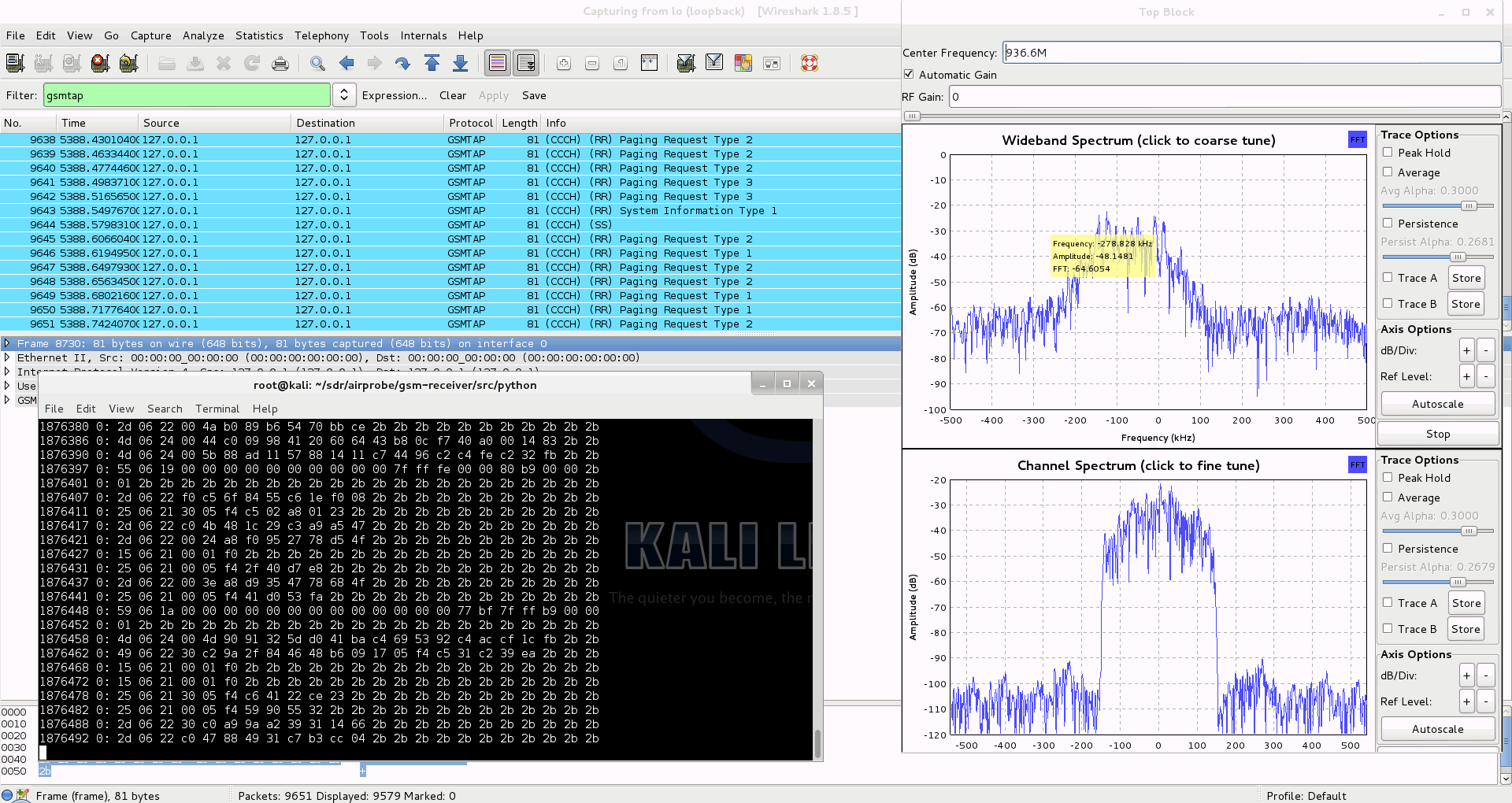
If you look at the traffic in Wireshark but it doesn’t seem to be right (for example you made a call or sent a text message while capturing but the Ciphering Mode Command is missing) it is pretty sure that you are using the wrong configuration (0b instead of 0c or vise versa). It is important to try both and figure out which one is correct for the cell you are observing.
I will assume you sent a text message to yourself while capturing data.
So now you can see all the messages of the beacon channel, but what are you looking for in the Wireshark log? It is quite simple: first a “Paging Request” for the TMSI of the target phone, then a “Ciphering Mode Command”. These are the messages which indicate that a transaction actually happened.
Now to continue with the flow it is best to try to decode the same cfile but now giving the key too to go.sh:
./go.sh capture.cfile 64 0C KEY
How to get the key? I already posted about that. Since we are testing using our own equipment we have access to the SIM card, so we can extract the key. It is best to extract the key immediately after you did a capture with RTL-SDR because depending on the network configuration the key could change.
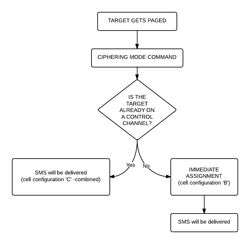
What are we looking for now? Well, it depends on the network: either there is an “Immediate Assignment” telling the phone to move to different timeslot (so they are not using the busy beacon channel to do their business) or you will actually be able to see the text message (easy to recognize: its protocol in Wireshark is ‘GSM SMS’), it will look like this:

If instead of the SMS you find an “Immediate Assignment” message you need to open it and see which timeslot the phone is being commanded to and then you need to decode that timeslot using go.sh. So, for example if it says that the phone needs to go to Timeslot 2 then your command would be:
./go.sh capture.cfile 64 2S KEY
Notice that I did not only change the Timeslot number from 0 to 2, but also the configuration from C to S, because the target phone is now on a Standalone Dedicated Control Channel (SDCCH), not on the beacon channel so we need to decode it differently.
Also worth noting that SMS messages are almost always sent on the Control Channel not on the Traffic Channel.
Here is a flowchart of the whole process to make it easier to understand (naturally since we can only see the downlink this shows only what happens on the downlink):
 Now that we were able to decode an SMS let’s get to something a little bit harder: decoding a voice call!
Well the first step is the same as it was when we decoded a text message: we look at the beacon channel, Timeslot 0:
./go.sh capture.cfile 64 0C
What do we expect to see? Nothing besides the “Cipher Mode Command” because we didn’t provide the key, so let’s do that:
./go.sh capture.cfile 64 0C KEY
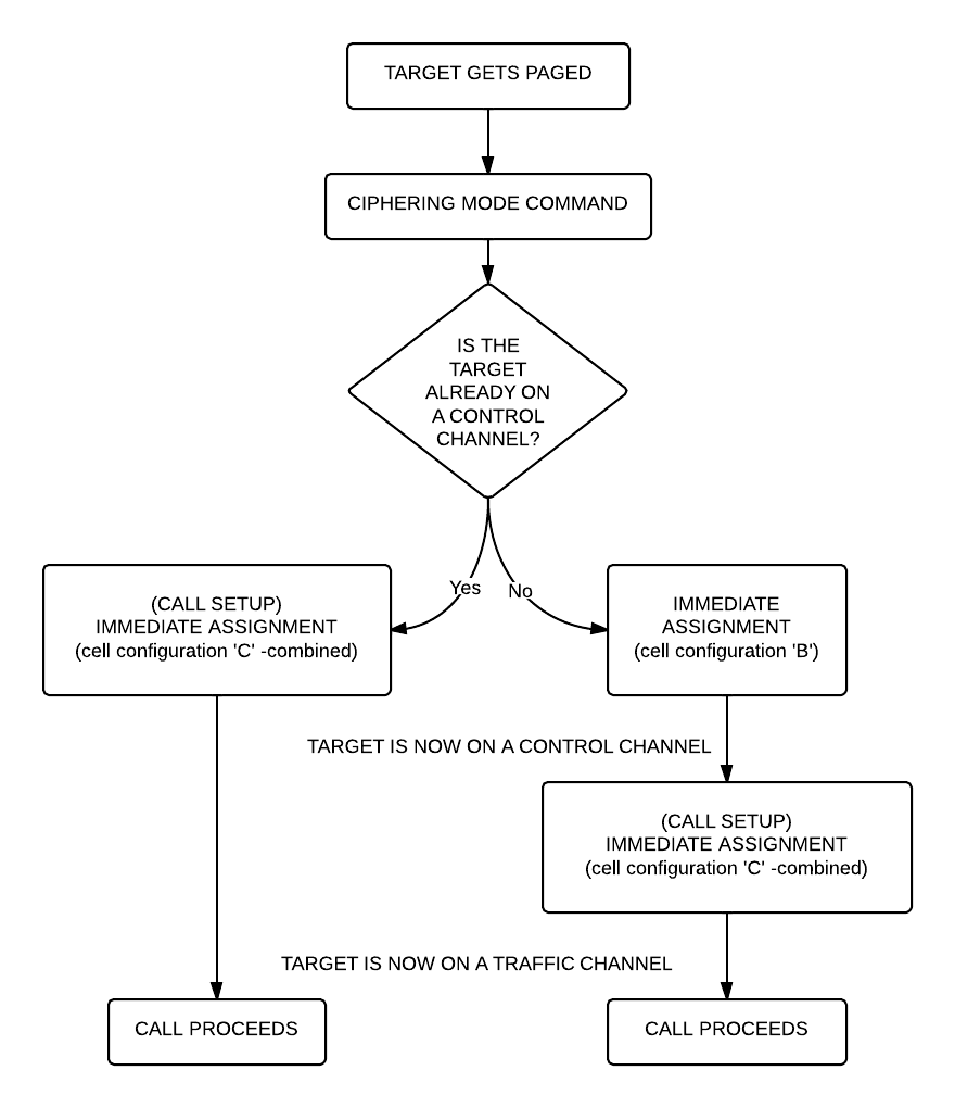
All right, what should we see now? Logically there needs to be an “Immediate Assignment” command, because the phone NEEDS to change at least once to a different timeslot to receive voice data (to a Traffic Channel, Timeslot 1-7). Â What we saw when decoding the SMS is correct here too: depending on the network configuration we can see some messages about the call setup (if it is an incoming call we can even see the caller ID – the phone number calling our target) then an “Immediate Assignment” (configuration ‘C’ – combined) or we can only see an “Immediate Assignment” directing the phone to a Control Channel (just like it happened when receiving an SMS, configuration ‘B’).
Of course if you follow the phone to the Control Channel you will see the call setup messages (in case of an incoming call) then another “Immediate Assignment” command, this time directing the phone to a Traffic Channel.
Here is again a flow chart showing the process:
Now there is only one question left: how do we decode the traffic channel to actually get the voice data?
Again, it is something that depends on the network: if the network uses simply Full Rate Speech then you can do the same what has been written in Srlabs’s tutorial:
./go.sh capture.cfile 64 1T KEY
What does this command do? It decodes Timeslot 1 as a Traffic Channel. We know what timeslot to decode from the “Immediate Assignment” command message, T means Full Rate Speech. The command results in a file called “speech.au.gsm”, which needs to be converted to .au file using ‘toast’:
toast -d speech.au.gsm
The resulting .au file could be played back using any player, e.g. cvlc (Command Line VLC):
cvlc speech.au
If you can not hear anything but beeps and other weird noises then there is a pretty good chance that the cell is using Enhanced Full Rate Speech instead of simple Full Rate Speech. To decode the channel as an Enhanced Full Rate Speech Traffic Channel:
./go.sh capture.cfile 64 1TE KEY
This results in a file called “speech.amr” which could be played back without any more modifications using for example Commandline VLC:
clvc speech.amr
If you have one hour to see everything in more detail, explained by a professional I would encourage you to watch this video:
UPDATE: I also uploaded my slides from Hacktivity.
Receiving, Decoding and Decrypting GSM Signals with the RTL-SDR - rtl-sdr.com
October 14, 2013 @ 06:09
[…] GSM signals with the RTL-SDR. Now blogger Domi has taken it further and has done an excellent big write up on his blog showing how to receive, decode, and also decrypt your own cell phone GSM si… with the […]
October 19, 2013 @ 00:40
Testing on my girlfriend mobile phone now ;). Great write-up! Excellent work!
October 19, 2013 @ 00:45
If she knows about and approved it then good luck. Otherwise expect law enforcement to show up pretty soon.
😉
October 20, 2013 @ 08:33
Evaluating GSM hopping
yo3iiu.ro/blog/?p=1069
I think this should work in RLT-SDR
October 20, 2013 @ 10:30
It could be possible, but the RTL-SDR’s bandwidth is quite limited, it’s around 3.5 MHz so I don’t think it is wide enough for this. But for sure this is a really cool research, respect to Bogdan!
One other way of defeating hopping is that since RTL-SDRs are really cheap you can use more of them making it possible to listen on every single ARFCN the phone could be hopping on (however bringing the data together from all these files needs to be researched it shouldn’t be that hard as far as I can see now).
October 22, 2013 @ 11:11
“I wasn’t able to find a way to use airprobe to capture my own cfile. I did find a way to capture one using ./rtl_sdr and GNU Radio however.”
This is easy to fix in gsm_receive_rtl.py, problem is that there is no output from the decoder gnuradio module that would go to the file sink. I can send you the fixed script if you wish.
October 23, 2013 @ 19:28
I actually kind of figured that out already but I quoted rtl-sdr.com word-by-word. It doesn’t really matter which tool is used to capture the data, it just needs to be captured and then fed into airprobe.
Thank you!
June 28, 2014 @ 09:02
I would appreciate a link to your fixed script!
October 23, 2013 @ 18:31
Gratulálok a munkádhoz, csak Ãgy tovább!
October 31, 2013 @ 23:52
Hey will you release your patched osmocom files ? or even write Step 5 capturing/decoding calls with osmocom software ?
November 1, 2013 @ 09:15
I haven’t done any work on decoding calls with Osmocom, so don’t expect any releases.
I just did some modifications based some other patches so I can monitor all pagings in a cell which makes it possible to link a TMSI to a phone number.
This code I am going to release soon.
November 1, 2013 @ 15:02
http://www.youtube.com/watch?v=r4VHs5Nf7Ho
maybe this looks interessting for you,
seems like he scripted some easy tool for doing the work.
November 1, 2013 @ 16:19
I saw that, but still it is not on my roadmap yet. Also I am not sure who is behind this video, and if it is fake or not, so I would not like to draw any conclusions based on it.
November 8, 2013 @ 16:12
I am using usrp1 et rtlsdr to capture traffic gsm connect notebook number 1
Number 2 notebook connected to motorola c115 and osmocom-bb project tools (osmocon,imobile,telnet).
I know my TMSI-channel arfncalc and Kc and run calls and sms.
I look at the captured traffic with Wireshark with command ./go.sh capture_traffic.cfile 64 -0C et ./go.sh capture_traffic.cfile 64 -0B
because I can not find my TMSI in the captured traffic ?
same problem to added my key Kc
November 10, 2013 @ 10:48
This test on the cell 1005 = 931.2 MHz
Thanks
November 10, 2013 @ 20:11
Do you see any traffic that looks valid?
It might be that beacuse of the inaccuracies of RTL-SDR you simple didn’t get much data.
Calibrating it and letting it warm up a little bit helps sometimes.
I struggle also quite a lot with it :(.
Also the command you run seems wrong: there should be no “-” in it.
November 11, 2013 @ 12:34
What will be better ?
some C139 motorla or SDR ?
November 13, 2013 @ 22:52
well, it depends on what you are willing to do with it
November 11, 2013 @ 21:44
no ……ok I was wrong to transcribe …
Iam good signal channel arfn ……
my test works like this:
1° notebook – osmocom-bb look at my channel arfn et TMSI and Kc
2° notebook connect usrp1 start capture on the channel bed arfn notebook 1
5-10 minutes to capture traffic and try to call the phone motorola c115 connected osmocm-bb or sms sent (notebook 1) to generating traffic …………… ok?
Stop capture and watch the traffic on wireshark
I run ./go.sh/tmp/prova.cfile 112 0C
I look if I see my TMSI
. / go.sh / tmp / prova.cfile 112 0C + my Kc
. / go.sh / tmp / prova.cfile 112 0B + my Kc
. / go.sh / tmp / prova.cfile 112 1S + my Kc
. / go.sh / tmp / prova.cfile 112 1T + my Kc
……result?
Do not decode anything
What I’m wrong?
November 13, 2013 @ 22:54
I am not really sure, could you try using gsm-receive_rtl.py and see if you can receive any GSM data with your stick?
November 14, 2013 @ 11:06
I have the same problem … I see the captured traffic with usrp is that rtlsdr
I see other TMSI, but I do not find that I have to try TMSI,
AirProbe it takes the additional patches?
my test with the phone to copy TMSI:
osmocom-bb + c115 + sim phone operator = telnet show = 1 ms = arfn example (1005) ……………………….. OK
telnet show my subscriber = kc ……………………… OK
1 sms number …..hello hello hello ….test message ..
call number 1 et speak …….. bla bla bla bla ……….. OK
The whole procedure was captured with usrp or rtlsdr on the copied channel example (1005)
AirProbe/gsm_receiver/src/python/./Go.sh/tmp/prova.cfile 112 0C + Kc for my usrp
AirProbe/gsm_receiver/src/python/./Go.sh/tmp/prova.cfile 64 0C + Kc for my rtlsdr
I can not find my sms decoded on wireshark
What’s wrong?
November 14, 2013 @ 11:13
Let’s start step by step:
1. Can you see any data at all when you decode your rtl-sdr file?
January 28, 2014 @ 00:32
try to capture trafic from two frequency Uplink and downlink of arfn
January 28, 2014 @ 08:44
You can do captureing but there is no decoding in airprobe for uplink data.
November 14, 2013 @ 16:53
I see you captured traffic on wireshark to other other TMSI:
captured with this example. / Go.sh / tmp / prova.cfile 64 0C
http://i.imgur.com/5LIjAq7.png
captured with this example. / Go.sh / tmp / prova.cfile 64 0B
http://i.imgur.com/YbWUuPp.png
November 23, 2013 @ 12:18
0C seems to be better to me because it has the periodicity that I usually look for , however it is still not looking 100% right to me.
It is possible, that your carrier uses a different setup, maybe one that is not implemented in airprobe.
If you look into the GSM for dummies PDF you can see that there are at least 4-5 different combinations of layouts for the beacon channel.
November 18, 2013 @ 05:20
Domi, any news so far about the stage of linking TMSI and phone number (part 3) via paging?
It’s very interesting indeed.
Thanks
November 23, 2013 @ 12:18
It will be posted soon, hopefully not later than tomorrow. Thanks for your patience!
November 26, 2013 @ 14:55
First of all, thank you very much for your effort! You’ve done a great job exposing GSM insecurity and I hope I’ll buy you a beer some time!
I’m a security enthusiast and I’m recently engaged in mobile security. This is my first day on GSM cracking and I’m currently trying to fit the pieces together.
Regarding the KC key, you’re poiting us out at https://domonkos.tomcsanyi.net/?p=369, which implies physical access to the terminal, but I quote srlabs.de, from their “Airprobe How-To” paper(https://srlabs.de/airprobe-how-to/):
“Choose a burst where the content of the frame is known and use it to find Kc. Use the Kraken tool to find Kc: https://lists.srlabs.de/pipermail/a51/2010-July/000688.html“. So, you just need the air captured bursts and the kraken tool to find out KC. Kraken is fed up with rainbow tables, right? Sorry if I’m mistaking anything.
Thank yiu and best regards!
November 26, 2013 @ 15:07
Correct, but finding the correct bursts requires deep knowledge of the network’s setup and GSM, definitely something a beginner will have trouble with.
However, again, you are correct to say that, I was able to crack a key using Kraken and the bursts I captured feom the air.
November 26, 2013 @ 15:40
Hello Domi!
Thank you for your reply! I’ve sent you an encrypted e-mail. My key ID is 0xC3B0D621.
Please don’t approve this comment.
Regards!
December 10, 2013 @ 19:10
Hi,
I have Airprobe and Wireshark working in Kali. The part I can’t seem to figure out is Kraken. I downloaded from https://opensource.srlabs.de/projects/a51-decrypt/wiki
When I run ./build.sh I get the following error:
a5cpu_test.cpp: In function ‘int main(int, char**)’:
a5cpu_test.cpp:44:16: error: ‘sleep’ was not declared in this scope
Kraken.cpp: In function ‘int main(int, char**)’:
Kraken.cpp:415:19: error: ‘usleep’ was not declared in this scope
ServerCore.cpp: In constructor ‘ServerCore::ServerCore(int, dispatch)’:
ServerCore.cpp:41:24: error: ‘close’ was not declared in this scope
ServerCore.cpp:49:24: error: ‘close’ was not declared in this scope
ServerCore.cpp: In destructor ‘ServerCore::~ServerCore()’:
ServerCore.cpp:72:24: error: ‘close’ was not declared in this scope
ServerCore.cpp: In member function ‘void ServerCore::Serve()’:
ServerCore.cpp:132:31: error: ‘close’ was not declared in this scope
ServerCore.cpp:149:46: error: ‘close’ was not declared in this scope
ServerCore.cpp: In destructor ‘ClientConnection::~ClientConnection()’:
ServerCore.cpp:218:14: error: ‘close’ was not declared in this scope
ServerCore.cpp: In member function ‘int ClientConnection::Write(std::string)’:
ServerCore.cpp:226:56: error: ‘write’ was not declared in this scope
ServerCore.cpp: In member function ‘int ClientConnection::Read(std::string&)’:
ServerCore.cpp:240:41: error: ‘read’ was not declared in this scope
Also, how do you point Kraken to the Tables on an external HD?
Thanks,
D
December 12, 2013 @ 10:36
Have you just downloaded the tables or you have already created the index files?
About your build error: I’m not sure but shouldn’t Kraken be built using make?
December 20, 2013 @ 04:13
Hi Dormi,
Sorry, I hadn’t seen your reply.
Yes I downloaded the tables and have the .dit files if that’s what you mean.
Trying to understand how to point Kraken or Find_kc to the .dit files in Linux?
I was able to install Kraken or rather, get the .cpp files turned into executables by modifying the files.
December 20, 2013 @ 04:14
Sorry! Domi 😉
December 22, 2013 @ 23:37
Try https://lists.srlabs.de/pipermail/a51/2010-July/000683.html
April 9, 2014 @ 22:39
Dsound: please post next time if you figure out a solution 🙂
#include in all cases worked well for me.
Domi: could you please copy the A51 tables to a drive (that I take to you) during my visit to Budapest? (~18.04.14)
Thank you for publishing this description I am planning for long to try this out.
April 9, 2014 @ 22:40
unistd.h
April 10, 2014 @ 07:56
Yes, that could be arranged, but please don’t forget that copying takes about 24 hours. Also it is very important that your HDD has 512 byte sectors, not 4096. You can check this with fdisk -l /dev/sdX
April 16, 2014 @ 15:44
I have checked, it is 512 bytes. If it is not too much effort I want to ask you to do it. Please write an email, if you think that you have time for this at the weekend.
Thank you!
April 17, 2014 @ 11:59
I’m not home this weekend, I’m sorry :/
December 19, 2013 @ 17:28
Hi Domi, this is great stuff ! I was wondering if you were able to get Airprobe to work with half rate traffic channels (TCH/H) ?
Regards
Sant
December 19, 2013 @ 18:58
Hey,
To do that you can simply follow the srlabs tutorial and use toast as far as I know.
December 31, 2013 @ 12:59
Hi Domi,
I’ve been trying to get speech out of an unencrypted non-hopping cfile without any success. I was able to get speech out of the srlabs tutorial cfile ( which is TCH/F) but all I get when I try to extract speech from my TCH/H cfile are conv_decode errors. I also see that airprobe has no input parameter for specifying which subslot to decode in a TCH/H timeslot. You need specify a subslot to differentiate between the two users sharing the timeslot. I can send you my cfile if you want to take a shot at it, but I’m pretty sure now that airprobe does not support half-rate traffic channels.
Regards,
Sant
December 31, 2013 @ 16:03
I am really sorry, I didn’t read your comment attentively enough. You are absolutely right (sadly), airprobe doesn’t support half-rate channels, only full rate and full rate enhanced.
December 19, 2013 @ 20:45
Hi,
I’m a rather new Linux user. How do I configure Kraken to work with the tables on a HD? Is there a config file to point to the tables?
December 31, 2013 @ 16:04
Try https://lists.srlabs.de/pipermail/a51/2010-July/000683.html
June 28, 2014 @ 08:27
great write-up! any idea why i’m only receiving GSMTAP and no GSM SMS? i saw this question asked on previous write-ups, but never answered. greatly appreciated!
July 22, 2014 @ 10:01
I’m not sure why, maybe your rtl-sdr just had ita hiccup when the sms was transferred? Or if you use encryption and didn’t provide the key…or you need to change to a different timeslot..
July 21, 2014 @ 10:57
Hai ….how 2 calibrate RTL-SDR stick? Rtl-sdr.com> Calibrate RTL-SDR with Mobile Phone or Cell Tower >that video not playing ( i receiving many errors like sch.c:260 ERR: conv_decode 12) please help me
thanks
dan
July 22, 2014 @ 10:05
Just install kal-rtlsdr then run kal and see its options. To fix the errors maybe a better antenna could be used
July 27, 2014 @ 15:55
im really new to linux, and srry if im askin this here in a pro forum
as i try to receive a live channel, it says there is no such file or directory..so where do i download this offline tool we call arfcncalc
July 31, 2014 @ 07:41
I’m not really sure you are running the right tool, it seems that it is trying to open a capture file instead of doing a live capture.
Arfcncalc could be downloaded from many places just search for it on Google.
July 30, 2014 @ 16:27
Hai,
Is it possible to run silent sms on my android 2.3.6(phone not Rooted)
July 31, 2014 @ 07:42
Root rights are needed to copy the apk onto the system partition, so no.
July 31, 2014 @ 10:30
Hi..i like this site thank you domi…What is ARFCN tool and why do I need it? “Find Your Own AFRCN Number *#0011# android-GSM”
July 31, 2014 @ 10:58
If you mean arfcn calc it is used to convert ARFCN numbers to actual frequencies
August 5, 2014 @ 03:54
Hi,
A5/0 no encryption? How does it work no 64-bit secret key kc ?
August 5, 2014 @ 08:32
Exactly, there is no key used, no encryption, only authentication.
August 6, 2014 @ 09:34
hello domi,
I Can’t Play speech.amr /speech.au Files The size of files 230 bytes/33bytes/ 140bytes etc…
August 6, 2014 @ 10:37
Why not?
August 17, 2014 @ 05:00
Which device is best for GSM sniffing? Osmocombb or RTL SDR
August 17, 2014 @ 23:13
I would get both.
August 21, 2014 @ 20:17
Have you come out with the python script for TMSI determination yet ? If not then how can i find my own TMSI from the mobile so that I can test the working ?
August 26, 2014 @ 21:27
No. It is quite easy to create, the method is known, so I don’t think I will publish it.
August 26, 2014 @ 21:17
hey domi,
You have not uploaded the tmsi_buster.py in github. Can you share a link to it ?? or if you can upload it @ github, then this thing will be complete.
August 26, 2014 @ 21:35
also your silent sms app, how do you use it to send silentsms from motorola c123 ? or have u added tat functionality to send silent sms in tmsi_buster.py
if that be the case i will request you to share the tmsi_buster.py
thanks again man, and gr8 job
cheers!!
January 14, 2016 @ 16:32
how to decrypt (decoding) the calls did you use FPGA or GPUs, if yes how many are they?,and how long did you take to crack it? please send me a detailed answer special thanx
April 18, 2017 @ 11:39
No FPGAs or GPUs were used.
March 10, 2016 @ 22:00
Good evening, I wanted to ask if this software you can also use it for another project, tetra osmocom,
It is using encryption air 1 tea2 TEA3 .. or say you need a different software as you use keys to 80bit? friendly and waiting for your answer
April 18, 2017 @ 11:38
I have no experience with Tetra, so can’t help you there. I’m certain it is a completely a different system.
May 6, 2016 @ 15:05
hi domi what are the specifications for the PC that you used for tables lookup (or cracking operation-getting Kc)
did you use particular GPUs for this ? how many are they ?
how long did it take?
did you use any FPGAs ? please send me a detailed answer 😀
thank you>>> 🙂
April 18, 2017 @ 11:37
Regular PC with a single 2TB disk attached would do it around 120-160 seconds. Using SSD arrays speeds up the process. After that you can increase the speed using GPUs. I think you can get it all the way down to 1-2 seconds. I haven’t used any FPGAs, not necessary in this case because the bottleneck is disk I/O (hence the usage of SSDs is recommended) not processing power.