The big GSM write-up – how to capture, analyze and crack GSM? – 4.
So. I had some requests asking me about how I did what I did with GSM. What tools did I use, what hardware and what options?
Since I believe strongly that GSM needs to be “out in the hands of the people†meaning everybody should have access to cheap hardware and free, opensource software that helps understanding GSM in practice I thought I will create a series of write-ups describing the whole process from the beginning.
Enjoy! ![]()
DISCLAIMER: EVERYTHING DESCRIBED HERE IS ONLY FOR EDUCATION PURPOSES. ONLY DECODE YOUR OWN DATA, NEVER TRY TO DECODE ANY DATA THAT IS NOT YOURS/YOU DON’T HAVE PERMISSION TO DECODE, RESPECT THE PRIVACY OF OTHERS!
I don’t take responsibility for how you use the konwledge you gained here.
Fourth step: Capture data with RTL-SDR, decode it with airprobe
As it could be read on RTL-SDR.com (I modified the original text with some enhancements):
Receive a Live Channel
First of all we need to find the frequency of the channel we are going to decode. There are a lot of both online and offline tools to convert an ARFCN number to actual frequency. Here I am going to use an offline tool called arfcncalc:
./arfcncalc -d -a ARFCNNaturally instead of ARFCN you need to specify the ARFCN number, the -d switch tells the program to give us the downlink frequency (-u would give us the uplink).
To decode a live channel using RTL-SDR type in terminal
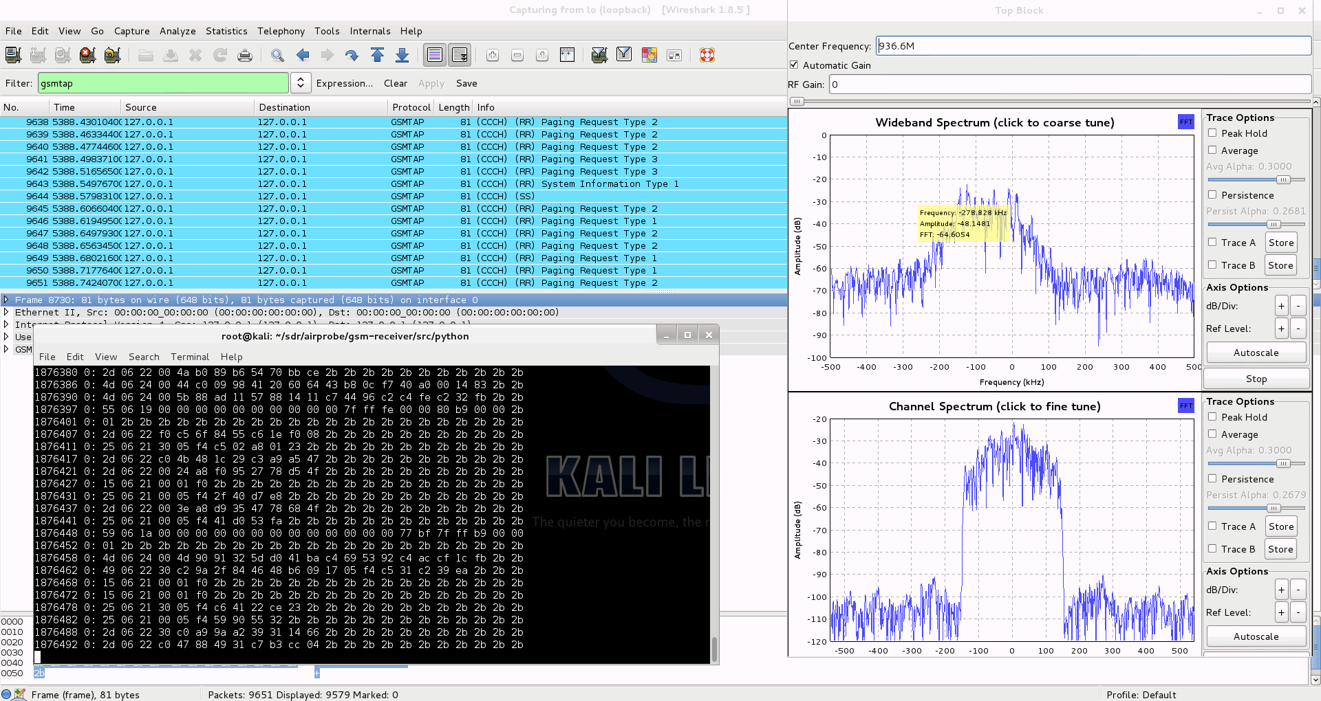
./gsm_receive_rtl.py -s 1e6 -f FREQUENCYA new window will pop up, click in the middle of the GSM channel in the Wideband Spectrum window. Within a few seconds some GSM data should begin to show constantly in wireshark. Type ./gsm_receive_rtl.py -h for information on more options. The -s flag is used here to set the sample rate to 1.0 MSPS, which seems to work much better than the default of 1.8 MSPS as it seems that there should be only one GSM peak in the wideband spectrum window.
If you have trouble getting data, but receive many errors like
sch.c:260 ERR: conv_decode 12then you should calibrate your RTL-SDR stick using the kalibrate-rtl program, described here.
After you determined the offset of your RTL-SDR calculate average of the different offset values. You will get something like this for example: +24.7 kHz. This actually is 24700 Hz, the plus means that the RTL-SDR tunes itself generally around 24700 Hz ABOVE the frequency you set it on, so you need to SUBTRACT this frequency from the result you got with ARFCNcalc. If your average offset is negative then naturally you need to ADD the average offset to the result of ARFCNcalc instead of subtracting it.
Use the new frequency to fire up RTL-SDR again, and let it warm up for some minutes. You should see some improvement compared to the first, uncalibrated test.
Capturing a cfile with the RTL-SDR (Added: 13/06/13)
I wasn’t able to find a way to use airprobe to capture my own cfile. I did find a way to capture one using ./rtl_sdr and GNU Radio however.
First save a rtl_sdr .bin data file using where -s is the sample rate, -f is the GSM signal frequency and -g is the gain setting. (rtl_sdr is stored in ‘gnuradio-src/rtl-sdr/src’)
./rtl_sdr /tmp/rtl_sdr_capture.bin -s 1.0e6 -f 936.6e6 -g 44.5Next, download this GNU Radio Companion (GRC) flow graph (scroll all the way down for the link), which will convert the rtl_sdr .bin file into a .cfile. Set the file source to the capture.bin file, and set the file output for a file called capture.cfile which should be located in the ‘airprobe/gsm-receiver/src/python’ folder. Also, make sure that ‘Repeat’ in the File Source block is set to ‘No’.
Now execute the GRC flow graph by clicking on the icon that looks like grey cogs. This will create the capture.cfile. The flow chart will not stop by itself when it’s done, so once the file has been written press the red X icon in GRC to stop the flow chart running.
After we have the cfile we can actually decode it just like as it was captured using a USRP, so you need to fire-up Wireshark listening on lo (localhost) and say:
./go.sh capture.cfile 64 0B
It will probably work for you just fine, data will flow into Wireshark as expected. The 64 is the decimation rate of the RTL-SDR, 0b is the configuration go.sh is going to use: 0 means Timeslot 0 (beacon channel), b is the configuration the cell uses on the beacon channel (see the ‘Signaling Channel Mapping’ in this chapter of ‘Introduction to GSM’ to see what this means).
Here are all the available configurations that are supported by airprobe:
     0C : TimeSlot0  "Combined configuration", with SDCCH/4
          (FCCH + SCH + BCCH + CCCH + SDCCH/4)
     0B : TS0  "FCCH + SCH + BCCH + CCCH"
     1S : TS1  SDCCH/8
     2T : TS2  (Full Rate) Traffic
     1TE: TS1  Enhanced Full Rate Traffic
If you look at the traffic in Wireshark but it doesn’t seem to be right (for example you made a call or sent a text message while capturing but the Ciphering Mode Command is missing) it is pretty sure that you are using the wrong configuration (0b instead of 0c or vise versa). It is important to try both and figure out which one is correct for the cell you are observing.
I will assume you sent a text message to yourself while capturing data.
So now you can see all the messages of the beacon channel, but what are you looking for in the Wireshark log? It is quite simple: first a “Paging Request” for the TMSI of the target phone, then a “Ciphering Mode Command”. These are the messages which indicate that a transaction actually happened.
Now to continue with the flow it is best to try to decode the same cfile but now giving the key too to go.sh:
./go.sh capture.cfile 64 0C KEY
How to get the key? I already posted about that. Since we are testing using our own equipment we have access to the SIM card, so we can extract the key. It is best to extract the key immediately after you did a capture with RTL-SDR because depending on the network configuration the key could change.
What are we looking for now? Well, it depends on the network: either there is an “Immediate Assignment” telling the phone to move to different timeslot (so they are not using the busy beacon channel to do their business) or you will actually be able to see the text message (easy to recognize: its protocol in Wireshark is ‘GSM SMS’), it will look like this:
If instead of the SMS you find an “Immediate Assignment” message you need to open it and see which timeslot the phone is being commanded to and then you need to decode that timeslot using go.sh. So, for example if it says that the phone needs to go to Timeslot 2 then your command would be:
./go.sh capture.cfile 64 2S KEY
Notice that I did not only change the Timeslot number from 0 to 2, but also the configuration from C to S, because the target phone is now on a Standalone Dedicated Control Channel (SDCCH), not on the beacon channel so we need to decode it differently.
Also worth noting that SMS messages are almost always sent on the Control Channel not on the Traffic Channel.
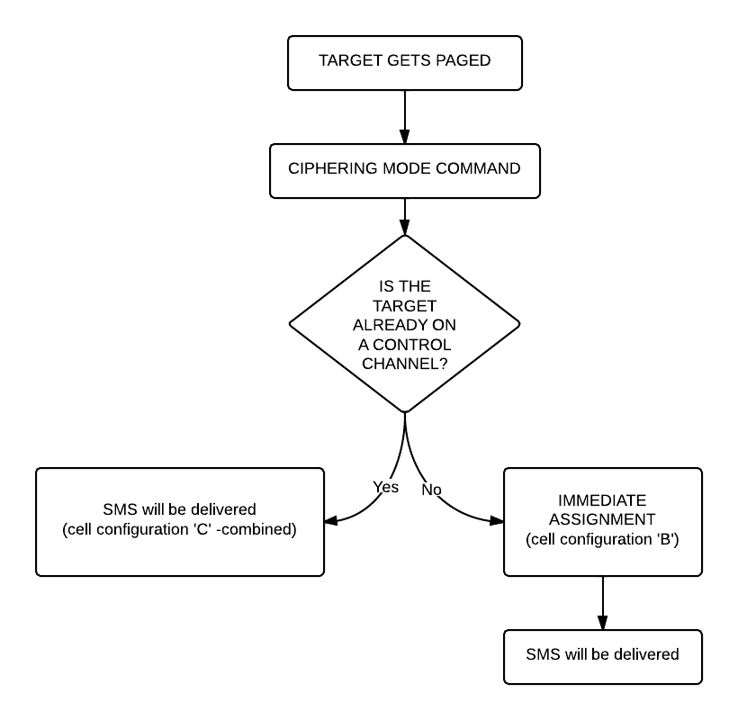
Here is a flowchart of the whole process to make it easier to understand (naturally since we can only see the downlink this shows only what happens on the downlink):
 Now that we were able to decode an SMS let’s get to something a little bit harder: decoding a voice call!
Well the first step is the same as it was when we decoded a text message: we look at the beacon channel, Timeslot 0:
./go.sh capture.cfile 64 0C
What do we expect to see? Nothing besides the “Cipher Mode Command” because we didn’t provide the key, so let’s do that:
./go.sh capture.cfile 64 0C KEY
All right, what should we see now? Logically there needs to be an “Immediate Assignment” command, because the phone NEEDS to change at least once to a different timeslot to receive voice data (to a Traffic Channel, Timeslot 1-7). Â What we saw when decoding the SMS is correct here too: depending on the network configuration we can see some messages about the call setup (if it is an incoming call we can even see the caller ID – the phone number calling our target) then an “Immediate Assignment” (configuration ‘C’ – combined) or we can only see an “Immediate Assignment” directing the phone to a Control Channel (just like it happened when receiving an SMS, configuration ‘B’).
Of course if you follow the phone to the Control Channel you will see the call setup messages (in case of an incoming call) then another “Immediate Assignment” command, this time directing the phone to a Traffic Channel.
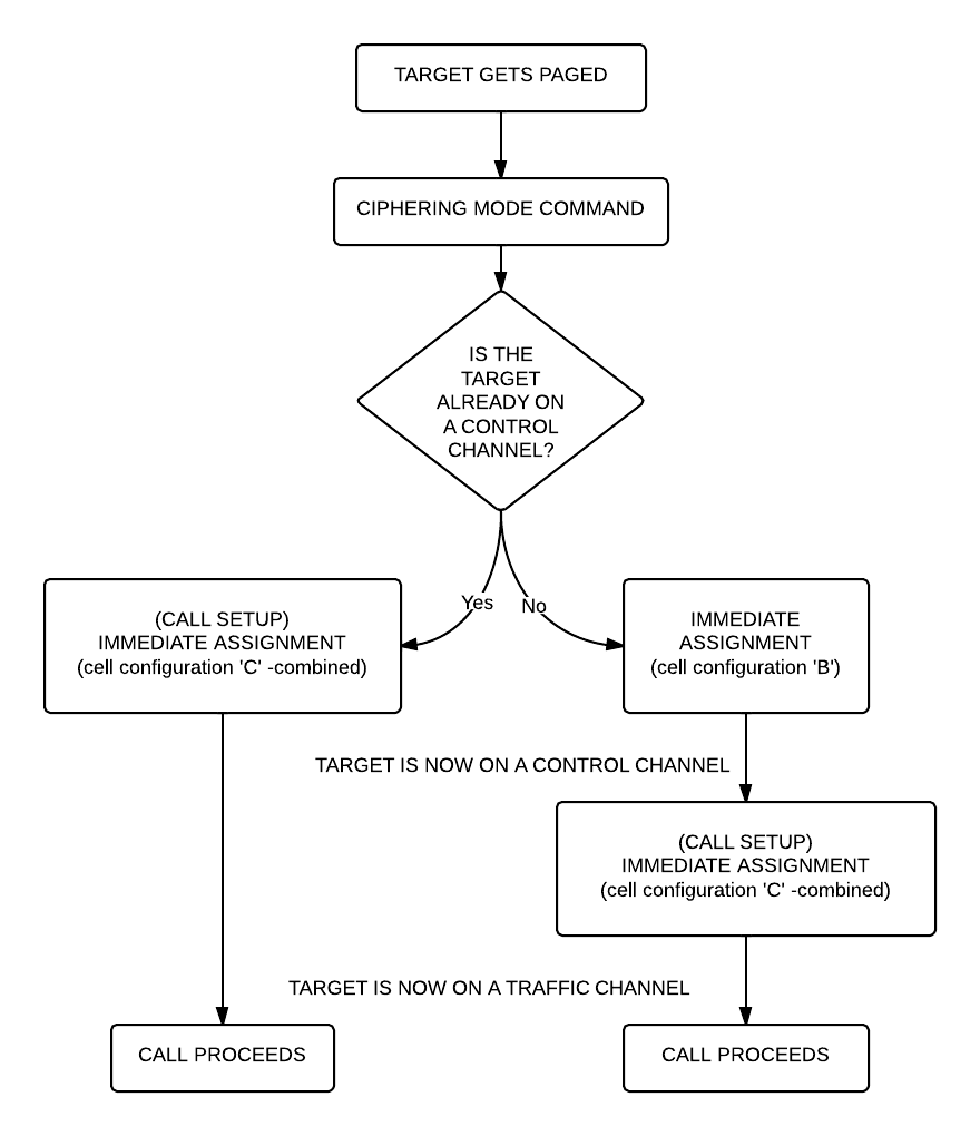
Here is again a flow chart showing the process:
Now there is only one question left: how do we decode the traffic channel to actually get the voice data?
Again, it is something that depends on the network: if the network uses simply Full Rate Speech then you can do the same what has been written in Srlabs’s tutorial:
./go.sh capture.cfile 64 1T KEY
What does this command do? It decodes Timeslot 1 as a Traffic Channel. We know what timeslot to decode from the “Immediate Assignment” command message, T means Full Rate Speech. The command results in a file called “speech.au.gsm”, which needs to be converted to .au file using ‘toast’:
toast -d speech.au.gsm
The resulting .au file could be played back using any player, e.g. cvlc (Command Line VLC):
cvlc speech.au
If you can not hear anything but beeps and other weird noises then there is a pretty good chance that the cell is using Enhanced Full Rate Speech instead of simple Full Rate Speech. To decode the channel as an Enhanced Full Rate Speech Traffic Channel:
./go.sh capture.cfile 64 1TE KEY
This results in a file called “speech.amr” which could be played back without any more modifications using for example Commandline VLC:
clvc speech.amr
If you have one hour to see everything in more detail, explained by a professional I would encourage you to watch this video:
UPDATE: I also uploaded my slides from Hacktivity.


