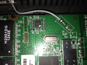
Linksys E900 serial port pinout
Lately I did some hacking with this router, and since I couldn’t find any information about the serial port and especially about its pinout I decided to publish what I found out.
First: to take the router apart you need to remove the 3 screws which holds it together. Two of them under the rubber feet which could be easily removed, the third is however a little bit tricky: you need to remove the little star-shaped rubber foot which is close to the right end of the router (if the ports are looking to the left).
After you removed all screws you need to apply some amount of force, and possible a flat screwdriver to crack the case open. Don’t worry, the plastic is quite durable, so give it some force if necessary.
Now if the ports are still facing your left then you will find the serial port at the top left corner of the PCB. It looks like someone just drilled 6 holes into the PCB. (see picture)
So now you only need to get some wires and a USB-TTL serial converter. The pinout (from top to bottom – ports still facing your left):
() ?
() TX
() RX
() ?
() ground
I haven’t done any testing with the ? holes since having only ground, RX and TX is enough. Now don’t forget, you need to connect your cable’s RX to the router’s TX and your TX to the router’s RX.
The correct settings for Putty are these:
Port: your COM port
Baud-rate: 115200
Data-bits: 8
Stop-bits: 1
Parity: None
Flow control: None
After you connect your adapter start Putty, then power up the router. You can see the boot-messages. If you hit Ctrl+C 4-5 times immediately after powering up the router you can stop the boot process and access the CFE menu.
